Secure JTAG with i.MX RT106x
JTAG is a powerful tool for testing and debugging embedded systems, but when unprotected, it can leave your devices vulnerable to threats like firmware extraction, memory tampering, and unauthorized access. Securing JTAG interfaces is key to keeping your systems safe and reliable. By protecting your devices at the hardware level, you not only safeguard your technology but also inspire confidence in your customers and strengthen your brand’s reputation. Make security a selling point because trust starts from the inside out.
Introduction
JTAG is a powerful tool for testing and debugging embedded systems, but when unprotected, it can leave your devices vulnerable to threats like firmware extraction, memory tampering, and unauthorized access. Securing JTAG interfaces is key to keeping your systems safe and reliable. By protecting your devices at the hardware level, you not only safeguard your technology but also inspire confidence in your customers and strengthen your brand’s reputation. Make security a selling point because trust starts from the inside out.
In this blog, we will introduce a real-world JTAG example with the NXP i.MX RT1060 Crossover MCU, which integrates a System JTAG Controller (SJC). We will then show how this can be configured to secure device access for the developer.
JTAG security modes
The NXP i.MX RT Series stands out for its combination of hardware-enforced security, flexible debug options, and strong tamper resistance, making it ideal for both development and deployed applications.
The i.MX RT1060 features an SJC that lets you control JTAG access through three security modes, which are set via OTP (One-Time Programmable) eFuses:
- Enabled mode provides low security and is the default mode of operation that allows normal debugging and free access to code.
- Secure mode offers strong security by controlling JTAG access with secret key challenge-response authentication. Every attempt to use the JTAG port is verified, and only authorized debug devices that provide the correct response are allowed access. Any unauthorized attempts to connect to the JTAG interface are blocked.
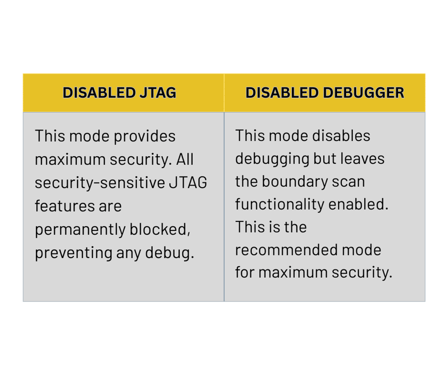
- Disabled mode offers the highest level of security by permanently blocking all sensitive JTAG functions. This completely prevents any debugging. This mode has two effects on both the JTAG interface and debugging as shown below
Simply put, eFuses are tiny memory blocks that are built into a chip and can only be programmed once. You can think of them like little electronic switches that, once turned on or “blown,” can never be changed again.
Why do we need eFuses?
eFuses act as the permanent enablers or disablers of JTAG access and define the applied security level. Secure JTAG uses these fuses to determine whether access should be allowed, denied, or gated by authentication. To this end, eFuses perform several important tasks:
- Assigning and storing Unique Device IDs (UDIDs) that help with device authentication and tracking
- Securely storing encryption keys that ensure only trusted, signed firmware can run
- Protecting firmware integrity by making sure only verified code gets executed on the device
- Making reverse engineering much harder
Challenge-Response Authentication
Challenge-response authentication is a security protocol where one side sends a challenge and the other side has to provide the correct response to prove its identity. It’s widely used in secure communication, like logging in or creating digital signatures, to block imposters and make sure only authorized parties can gain access.
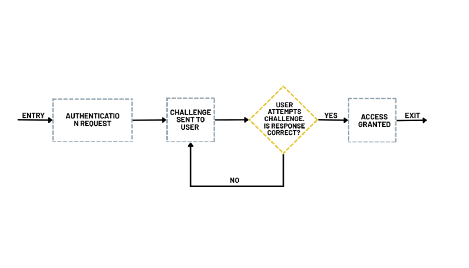
the main steps within the challenge-response authentication process are as follows, with the diagram below illustrating the typical mechanism in practice:
- Challenge: The system presents a test to the user or device requesting access. It could be a question or a cryptographic puzzle, for example.
- Response: The user or device replies with the appropriate answer, such as a password, security token, or cryptographic proof.
- Validation: The system examines the reply to confirm whether it matches the expected result.
- Authentication: If the response checks out, the user is successfully authenticated and allowed to proceed.
Programming Secure JTAG eFuses
In this demo, we will be using NXP MCU Boot Utility to program our eFuses and SEGGER J-Link Commander to connect to the i.MX RT1060 when using Secure JTAG for debugging. If no key has been provided, the JTAG interface will stay locked.
When performing these operations, it is very important to consider the following:
- Putting the i.MX RT1060 chip into Secure JTAG mode requires carefully programming the right fuses.
- This operation is irreversible, so you need to be sure that everything is correctly configured before burning the eFuses.
The official GitHub releases are Windows .exe builds, for that you can install the MCU utility by using the following steps if you are running Ubuntu on your computer.
Step 1: Set up the environment
First, we Install Wine:
bea@bea-Thin-GF63-12UCX:~$ sudo dpkg --add-architecture i386bea@bea-Thin-GF63-12UCX:~$ sudo apt updateHit:1 https://packages.microsoft.com/repos/code stable InReleaseHit:2 http://tn.archive.ubuntu.com/ubuntu noble InReleaseHit:3 http://security.ubuntu.com/ubuntu noble-security InReleaseHit:4 http://tn.archive.ubuntu.com/ubuntu noble-updates InReleaseHit:5 http://tn.archive.ubuntu.com/ubuntu noble-backports InReleaseGet:6 http://tn.archive.ubuntu.com/ubuntu noble/main i386 Packages [1,041 kB]Get:7 http://security.ubuntu.com/ubuntu noble-security/main i386 Packages [316 kB]Get:8 http://security.ubuntu.com/ubuntu noble/restricted i386 Packages [14.7 kB]Get:9 http://tn.archive.ubuntu.com/ubuntu noble/universe i386 Packages [8,514 kB]Get:10 http://security.ubuntu.com/ubuntu noble-security/restricted i386 Packages [17.6 kB]Get:11 http://security.ubuntu.com/ubuntu noble-security/universe i386 Packages [543 kB]Get:12 http://security.ubuntu.com/ubuntu noble-security/multiverse i386 Packages [3,588 B]Get:13 http://tn.archive.ubuntu.com/ubuntu noble/multiverse i386 Packages [126 kB]Get:14 http://tn.archive.ubuntu.com/ubuntu noble-updates/main i386 Packages [506 kB]Get:15 http://tn.archive.ubuntu.com/ubuntu noble-updates/restricted i386 Packages [20.0 kB]Get:16 http://tn.archive.ubuntu.com/ubuntu noble-updates/universe i386 Packages [677 kB]Get:17 http://tn.archive.ubuntu.com/ubuntu noble-updates/multiverse i386 Packages [7,572 B]Get:18 http://tn.archive.ubuntu.com/ubuntu noble-backports/main i386 Packages [32.6 kB]Get:19 http://tn.archive.ubuntu.com/ubuntu noble-backports/universe i386 Packages [15.6 kB]Fetched 11.8 MB in 6s (2,127 kB/s)Reading package lists... DoneBuilding dependency tree... DoneReading state information... Done480 packages can be upgraded. Run 'apt list --upgradable' to see them.bea@bea-Thin-GF63-12UCX:~$ sudo apt install wine64 wine32Reading package lists... DoneBuilding dependency tree... DoneReading state information... DoneE: The package mcuxpressoide needs to be reinstalled, but I can't find an archive for it.If you encounter this error, try installing the MCUXpresso IDE, which can be found on the NXP website https://www.nxp.com/mcuxpresso/ide
Once this is done, run the following commands:
sudo chmod +x mcuxpressoide-25.6.136.x86_64.deb.bin ./mcuxpressoide-25.6.136.x86_64.deb.binYou can now run MCU Boot Utility with Wine
- Download the latest NXP MCU Boot Utility from the following github repo: https://github.com/nxp-mcuxpresso/mcu-boot-utility/releases
- Extract it:
unzip mcu-boot-utility-3.4.0-with-exe.zip cd mcu-boot-utility-3.4.0-with-exe/bin- And run it:
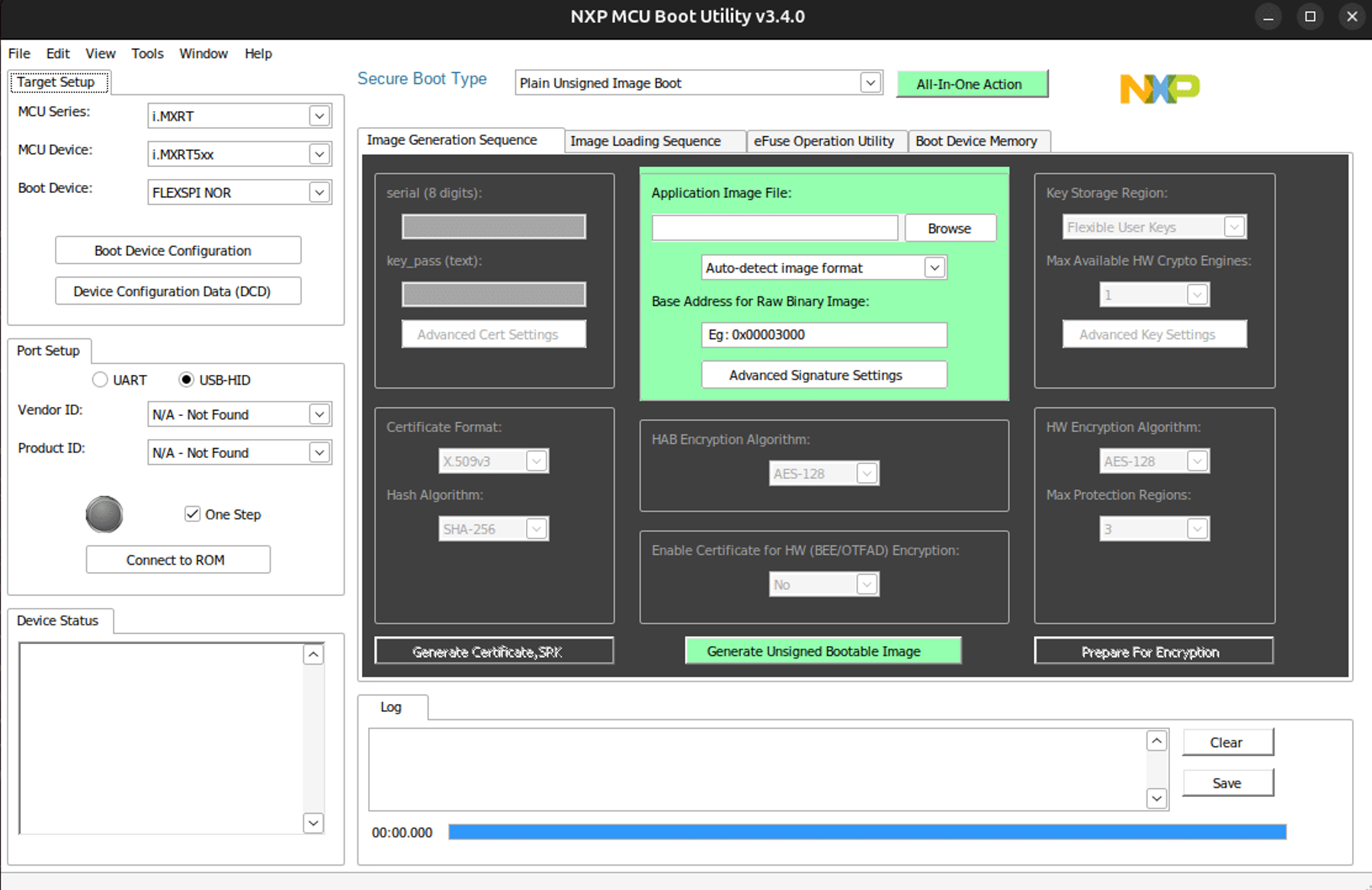
wine NXP-MCUBootUtility.exeYou should now see this GUI, which means you are ready to start the real work.
Step 2: Configuring and securing the i.MX RT106x MCU using eFuses to enable Secure JTAG access
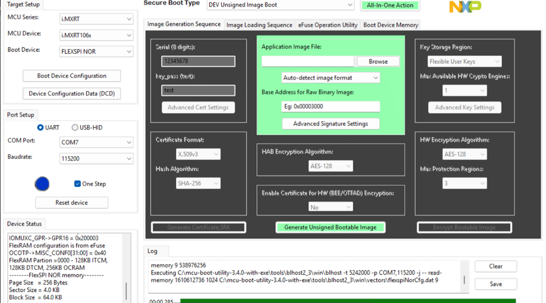
Select the i.MX RT106x MCU and choose UART as your connection port. If you encounter the following connection error, it likely means the MCU is not in Serial Downloader Mode.

To enable this mode, we need to configure the BMOD pins using the SW7 DIP switch:
- BMOD0 = 1 means you set SW7 pin 1 to ON
- BMOD1 = 0 means you set SW7 pin 2 to OFF
Now let’s connect:
Go to eFuse Operation Utility tab:
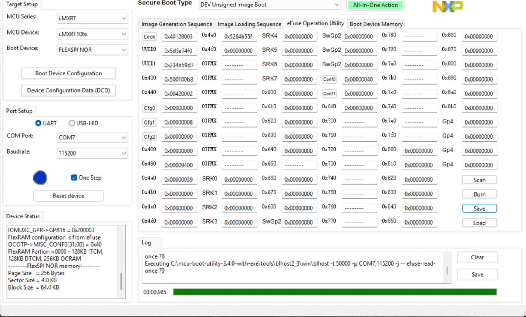
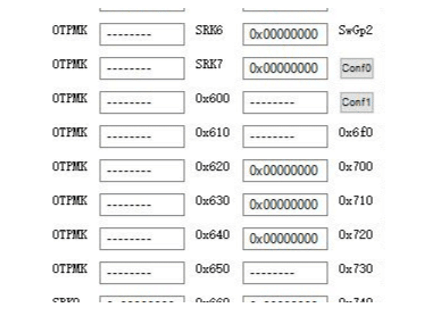
Now let’s take a look at the eFuse settings related to the Secure JTAG that NXP provides:
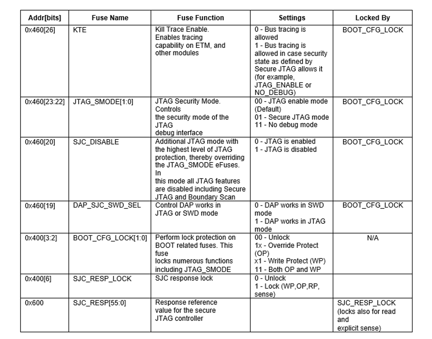
Following the table above and the steps below, we can program the necessary values into the appropriate eFuses to enable Secure JTAG mode:
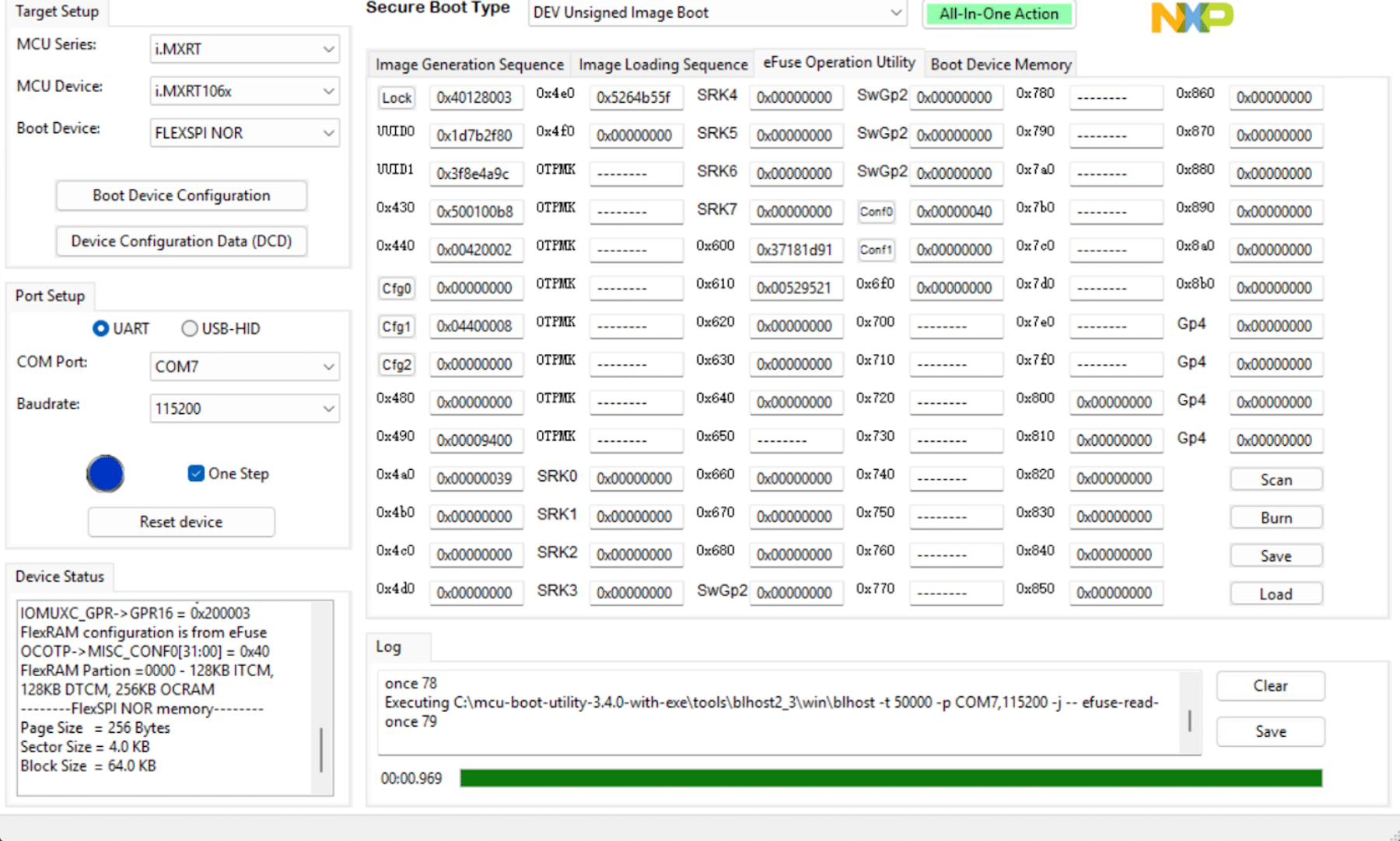
- The UUID programmed is 3f8e4a9c1d7b2f80
- Read and backup the 64-bit “challenge” value stored in the eFuse UUID0, located at address 0x410 and UUID1 located at 0x420:
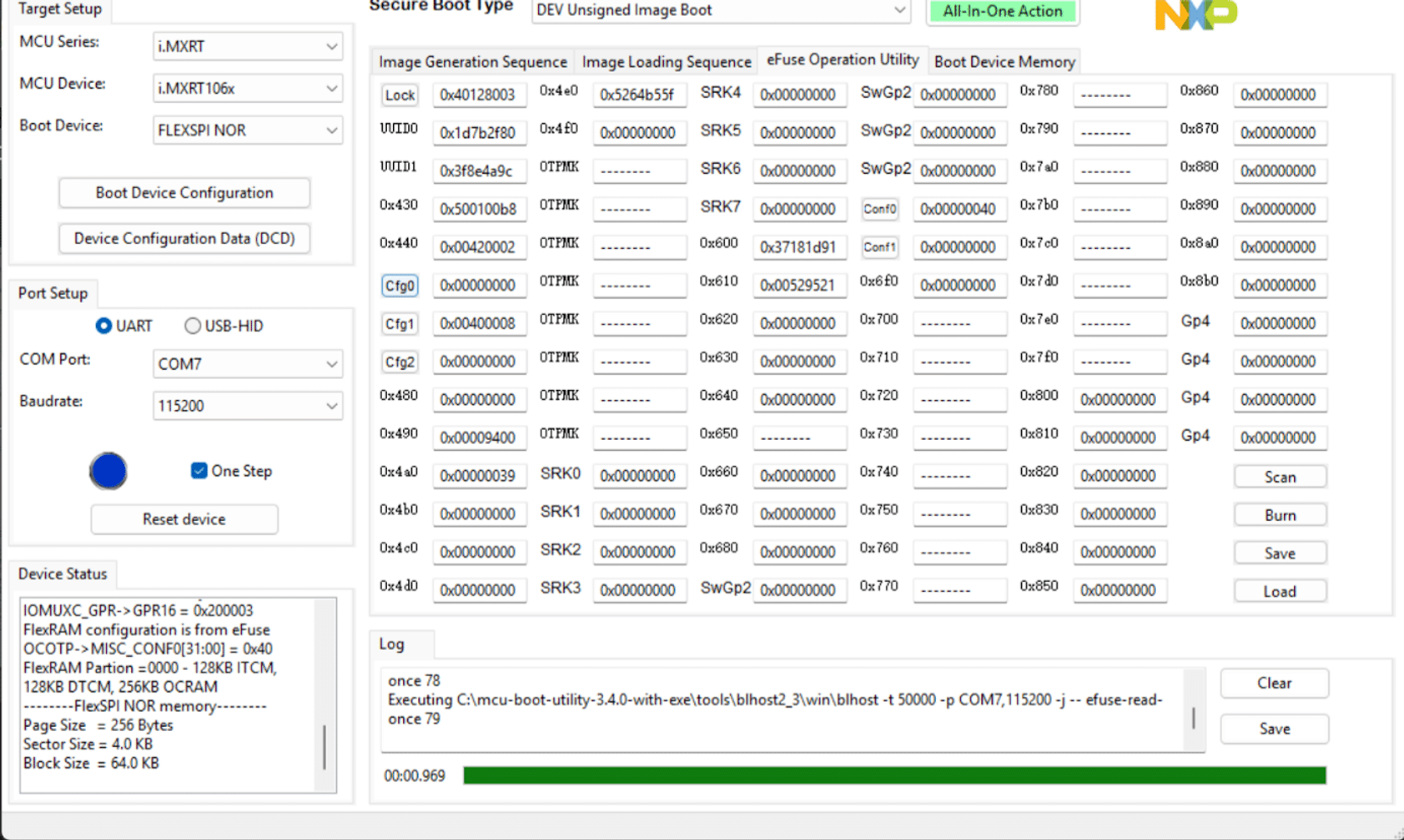
3. Program a 56-bit (7-Byte) secret response key in the eFuse SJC_RESP, at locations (0x610, 0x600). In our example, the secret response key is 52952137181d91
Here, we have created a secret key which is a unique sequence of bytes that serves as a password or token for our device. This key will be programmed into the device’s eFuses. Since eFuses can only be programmed once and cannot be changed afterward, it’s essential to securely back up this key outside the device to ensure that we don’t lose access.
4. During this step, refer to the eFuse settings table to know where each eFuse is located.
- Set the DAP_SJC_SWD_SEL eFuse to 0x1 to switch the debug port from the usual SWD mode to JTAG mode.
- Next, program 0x1 into the JTAG_SMODE eFuse to turn on Secure JTAG mode, adding an extra layer of protection.
- Then, set the KTE_FUSE eFuse to 0x1 this helps activate the security features tied to the keys.
- Finally, program 0x1 into the eFuse SJC_RESP_LOCK
This locks the secret response key that you programmed earlier, making it permanent and unchangeable.
After completing this process, the SJC_RESP field becomes hidden, as well as the response key, which can no longer be read or modified in the fuse map.
Be careful when burning eFuses. Always test authentication before locking and finalizing.
Step 3: Connecting the i.MX RT106x MCU over Secure JTAG using the SEGGER J-Link tool
Next, we will be using the SEGGER J-Link debug tool to debug the system after enabling the Secure JTAG. For this demo, I used J-Link Commander V8.86, but you can grab a different version of SEGGER J-Link Commander from the following link: SEGGER – The Embedded Experts – Downloads – J-Link / J-Trace
To start with, let’s launch J-Link Commander and connect to the device. If you are new with SEGGER J-Link Commander, follow this link to learn more about its commands: J-Link Commander – SEGGER Knowledge Base
Before installing JLink on your machine run this command first because JLink has these dependencies and make sure you have same results
You may encounter this error when you try to unpack Jlink as follows
dpkg: error: requested operation requires superuser privilegebea@bea-Thin-GF63-12UCX:~/Downloads$ sudo dpkg -i JLink_Linux_V886_i386.deb[sudo] password for bea:(Reading database ... 372987 files and directories currently installed.)Preparing to unpack JLink_Linux_V886_i386.deb ...Removing /opt/SEGGER/JLink ...Unpacking jlink:i386 (8.86.0) over (8.44.0) ...dpkg: dependency problems prevent configuration of jlink:i386: jlink:i386 depends on libxcb-render-util0 (>= 0.3.8). jlink:i386 depends on libxcb-shape0 (>= 1.9). jlink:i386 depends on libxcb-icccm4 (>= 0.3.9). jlink:i386 depends on libxcb-keysyms1 (>= 0.3.9). jlink:i386 depends on libxcb-image0 (>= 0.3.9). jlink:i386 depends on libxkbcommon-x11-0 (>= 0.5.0). jlink:i386 depends on libsm6 (>= 1:6.0.4). jlink:i386 depends on libc6 (>= 1:6.3.5). dpkg: error processing package jlink:i386 (--install): dependency problems - leaving unconfiguredErrors were encountered while processing: jlink:i386Here is what you will do to install dependencies
sudo apt-get install libxcb-render-util0:i386sudo apt --fix-broken installsudo dpkg -i JLink_Linux_V886_i386.debYou can run this command to locate the JLink commander
sudo find / -name JLinkExe 2>/dev/nullYou will find something like this
/usr/bin/JLinkExe/opt/SEGGER/JLink_V886/JLinkExeNow simply run JlinkExe from terminal and wait to be connected to target
bea@bea-Thin-GF63-12UCX:/opt/SEGGER/JLink_V886$ JLinkExe SEGGER J-Link Commander V8.86 (Compiled Nov 12 2025 12:20:48) DLL version V8.86, compiled Nov 12 2025 12:19:46Connecting to J-Link via USB...O.K.To test debugging with Secure JTAG, we’ll use a JLINKScript, which is a small script for the SEGGER J-Link debugger that defines how to communicate with our target device. This includes sending the response key during authentication, exactly as required in this demo.
SEGGER provides a list of templates that helps in creating custom J-Link script files which was our starting point. Please have a look the ones provided by SEGGER https://kb.segger.com/J-Link_script_files#J-Link_script_file_examples In our case our starting point was the script provided by NXP Community support kerryzhou Tech support who has given a great explanation . We invite you to have a look in here as well following this link RT106X secure JTAG test and IDE debug – NXP Community.
Download and Rename the script depending on your target , copy it under this path /opt/SEGGER/JLink_V886/ , update the InitTarget() with your keys.
This is how the SEGGER J-link Secure JTAG unlock script looks like
int InitTarget(void) { int v; unsigned int Key0; // First 32 bits of the 56-bit response key unsigned int Key1; // Last 24 bits of the 56-bit response key (upper byte unused) JLINK_SYS_Report("***********************************************"); JLINK_SYS_Report("* NXP i.MX RT106x - Secure JTAG Test Script *"); JLINK_SYS_Report("***********************************************"); // --- Configure your own secret key here --- // Replace with YOUR unique 56-bit response key Key0 = 0x37181d91; // Example lower 32 bits Key1 = 0x529521; // Example upper 24 bits (MSB byte should be 0) // ------------------------------------------- // Tell J-Link how to talk to the deviceJLINK_CORESIGHT_Configure("IRPre=0;DRPre=0;IRPost=0;DRPost=0;IRLenDevice=5"); CPU = CORTEX_M7; // Prompt: Set BMOD pins to boot in JTAG mode JLINK_SYS_Report("Set pin JTAG_MOD => 1"); JLINK_SYS_Sleep(100); // --- Request Challenge from SJC --- JLINK_JTAG_WriteIR(0xC); //Output the Challenge (UUID) JLINK_SYS_Report("Reading Challenge UUID..."); // Read UUID0 (lower 32 bits) JLINK_JTAG_StartDR(); JLINK_JTAG_WriteDRCont(0xFFFFFFFF, 32); v = JLINK_JTAG_GetU32(0); JLINK_SYS_Report1("Challenge UUID0:", v); // Read UUID1 (upper 32 bits) JLINK_JTAG_WriteDREnd(0xFFFFFFFF, 32); v = JLINK_JTAG_GetU32(0); JLINK_SYS_Report1("Challenge UUID1:", v); // --- Send Response Key --- JLINK_JTAG_WriteIR(0xD); // Accept the Response Key from the debugger JLINK_SYS_Report("Sending Response Key..."); // Send first 32 bits JLINK_JTAG_StartDR(); JLINK_JTAG_WriteDRCont(Key0, 32); // Send remaining 24 bits JLINK_JTAG_WriteDREnd(Key1, 24); // Prompt: Return to normal mode JLINK_SYS_Report("Change pin JTAG_MOD => 0"); JLINK_SYS_Report("Secure JTAG authentication sequence completed."); return 0;}This script will read the challenge value we put into eFuse UUID0 and UUID1 locations 0x410 and 0x420 and should provide the appropriate response to the SJC for an authentication match.
The debugger must send the correct response key after receiving the challenge to unlock the JTAG interface. If you can see the reading challenge ID is there then all is good.
Run the script using this command :
JLinkExe -JLinkScriptFile NXP_RT1060_SecureJTAG.JlinkScript -device MIMXRT1064XXX6A -if JTAG -speed 4000 -autoconnect 1 -JTAGConf -1,-1Once this command is executed, you connect to the target and you will get the following output in your terminal
License(s): RDI, FlashBP, FlashDL, JFlash, GDB VTref=3.29V Device "MIMXRT1064XXX6A" selected. Connecting to target via JTAGInitTarget() start************************************************ NXP i.MX RT106x - Secure JTAG Test Script ************************************************ Set pin JTAG_MOD => 1The JTAG_MODE signal is attached to a physical pin that you can pull high or low to tell the chip which debug interface mode to use at reset. For this step, The JTAG_MODE should be pulled HIGH.
Just after pulling up the PIN , Jlink script will read the challenge
Connecting to target via JTAGInitTarget() start************************************************ NXP i.MX RT106x - Secure JTAG Test Script ************************************************TotalIRLen = 5, IRPrint = 0x01JTAG chain detection found 1 devices:#0 Id: 0x2085C01D, IRLen: 04, JTAG-DPReading Challenge ID...Challenge UUID0:0x1D7B2F80Challenge UUID1:0x3F8E4A9C Set pin JTAG_MOD => 0If you get the following info message, pull down the JTAG_MODE assigned pin.
Once this is done the InitTarget() will end and you are back on track.
************************************************ NXP i.MX RT106x - Secure JTAG Test Script ************************************************TotalIRLen = 5, IRPrint = 0x01JTAG chain detection found 1 devices:#0 Id: 0x2085C01D, IRLen: 04, JTAG-DPReading Challenge ID...Challenge UUID0:0x1D7B2F80Challenge UUID1:0x3F8E4A9CInitTarget() endNow that the device has been authenticated with the challenge-response mechanism, we can use the JTAG debugger just as we usually would.
This is the expected final output
************************************************ NXP i.MX RT1060 - Secure JTAG Test Script ************************************************TotalIRLen = 5, IRPrint = 0x01JTAG chain detection found 1 devices:#0 Id: 0x2085C01D, IRLen: 04, JTAG-DPReading Challenge ID...Challenge UUID0:0x1D7B2F80Challenge UUID1:0x3F8E4A9CInitTarget() endTotalIRLen = 4, IRPrint = 0x01JTAG chain detection found 1 devices: #0 Id: 0x0BC40277, IRLen: 04, CoreSight JTAG-DP DPIDR: 0x0BC40277 CoreSight SoC-400 or earlier Scanning AP map to find all available APs AP[3]: Stopped AP scan as end of AP map has been reached AP[0]: AHB-AP (IDR: 0x24770014) Iterating through AP map to find AHB-AP to use AP[0]: Core found AP[0]: AHB-AP ROM base: 0xE00FD000 CPUID register: 0x411FC271. Implementer code: 0x41 (ARM) Found Cortex-M7 r1p1, Little endian. FPU: 8 code (BP) slots and 0 literal slots I-Cache present CoreSight components: ROMTbl[0] @ E00FD000 [0][0]: E00FF000 CID B105100D PID 000BB4C8 ROM Table ROMTbl[1] @ E00FF000 [1][0]: E00FF000 CID B105100D PID 000BB4C7 ROM Table ROMTbl[2] @ E00FF000 [2][0]: E00E0000 CID B105E00D PID 000BB00C SCS-M7 [2][1]: E0001000 CID B105E00D PID 000BB002 DWT [2][2]: E0002000 CID B105E00D PID 000BB000 FPB-M7 [2][3]: E0003000 CID B105E00D PID 000BB001 ITM [2][4]: E0004000 CID B105900D PID 001BB975 ETM-M7 [2][5]: E0042000 CID B105900D PID 004BB906 CTI [2][6]: E0043000 CID B105900D PID 001BB980 TPIU-M7 [2][7]: E0041000 CID B105900D PID 001BB901 TSG Cache: Separate I- and D-cache. I-Cache L1: 32 KB, 256 Sets, 32 Bytes/Line, 2-Way D-Cache L1: 32 KB, 256 Sets, 32 Bytes/Line, 4-Way Mem zones: Zone: 'Default' Description: Default access mode Cortex-M7 identified. J-Link>Closing
In this blog, we explored JTAG and its various security levels before walking through the steps to put a device into secure mode and still debug it safely. We also highlighted how developers can protect their devices by enabling Secure JTAG mode, using authentication mechanisms and fuse-based configurations to ensure that debugging can be achieved without threatening your device.
References
- i.MX RT1060 Processor Reference Manual
- RT106X secure JTAG test and IDE debug – NXP Community
- AN4686: Secure Debug in i.MX 6/7/8M Family of Applications Processors | NXP Semiconductors
- https://github.com/nxp-mcuxpresso/mcu-boot-utility?tab=readme-ov-file
- JTAG technology, JTAG security, JTAG applications
- https://kb.segger.com/J-Link_script_files